
This second tutorial on digital capacitive load cell systems aims to give the user a brief overview of the powerful diagnostic tools available with this system. This diagnostic capability is an attractive one because it doesn’t allow operators to make any changes to the system while they are troubleshooting a problem.
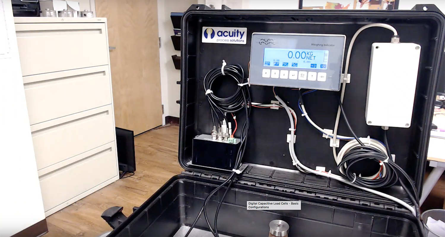
1. As seen in our first tutorial, this overview of an Alfa Laval capacitive load cell system describes one which has been setup in a briefcase to use as a display. The photo above shows the lid of the briefcase containing the measuring system’s display, the power system, and the weighing module.
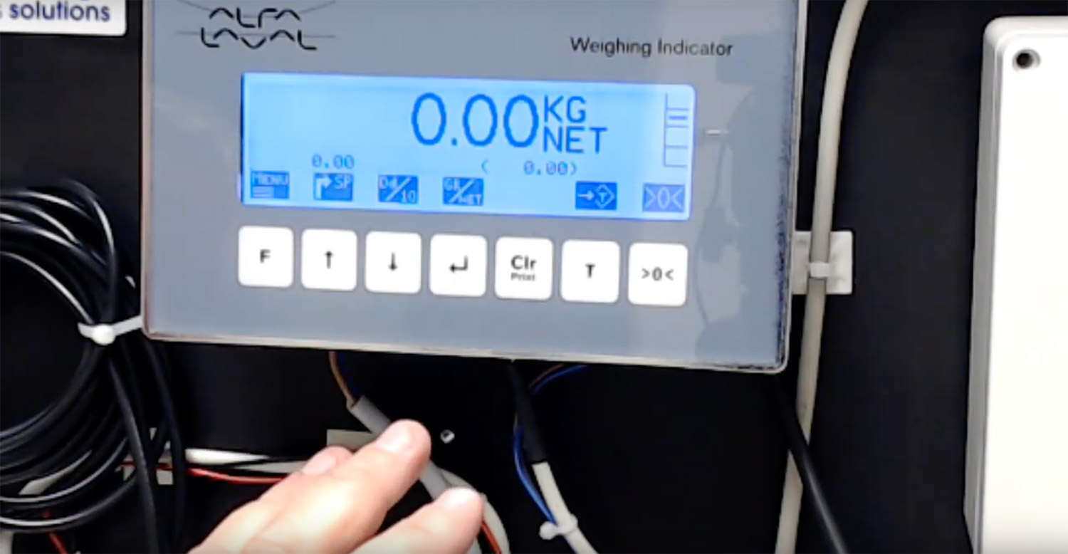
2. A closer look shows the screen and the touch keys below. By pushing the Menu Button, the menu key, a menu will appear on the left-hand side of the screen.
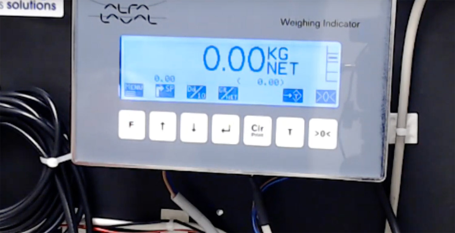
3. This menu can be navigated by using the UP and the DOWN keys, and operators select a particular option by hitting the return RETURN key.

4. By selecting the “system info” option on the menu, the above screen appears. The first information that is shown is the version of software that is being used. In addition, there is an event timer that shows how many times the system has been turned on and off.

5. By hitting the menu button again, another menu will emerge.

6. By selecting “system”, operators can see as well as set the date and time. By pushing on the Menu Button again, the system takes us to the previous screen.

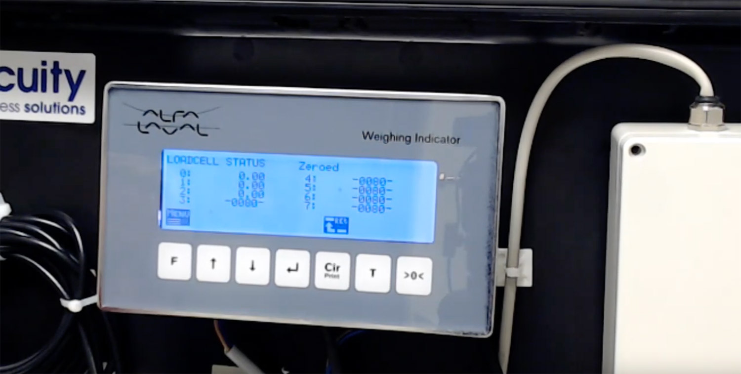
7. By navigating to the load cell screen, the operators can see all of the load cells that are connected to the system. The numbers 0 through 7 indicate each unique load cells, and there can be up to 8 load cells connected to the system.
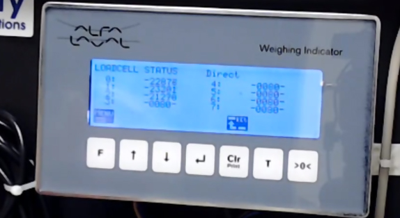
8. In this case, we see three load cells are connected. The weight is being displayed in “Direct Mode” which is a dimensionless number generated within the load cells. As force is applied to the system, these numbers change as the degree of force changes.

9. By selecting menu again, operators can choose “Direct”, “Weight”, or “Zeroed” options. “Direct” is the dimensionless number that was mentioned earlier. The “Weight” option shows the true load on the cells (in the video, this number is negative because the system was coarsetared with a weighing plate on it, and it had been removed during the demonstration). “Zeroed” shows the load cell readout after the system has been zeroed.
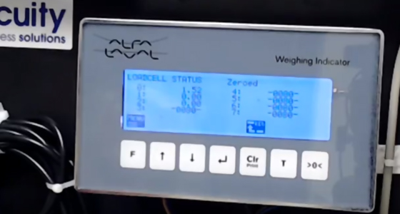
10. The zeroed option allows gives us the number that results after being zeroed out; for example, showing only the weight of anything that is being added to the tank, as shown above.
These features offer a significant benefit when evaluating a system installation. For example, if two of the cells are reading a positive number and the third reads a negative number, it is generally indicative of an installation problem that should be checked.
Leave a Reply
You must be logged in to post a comment.